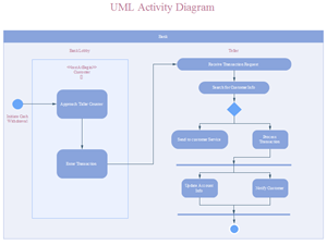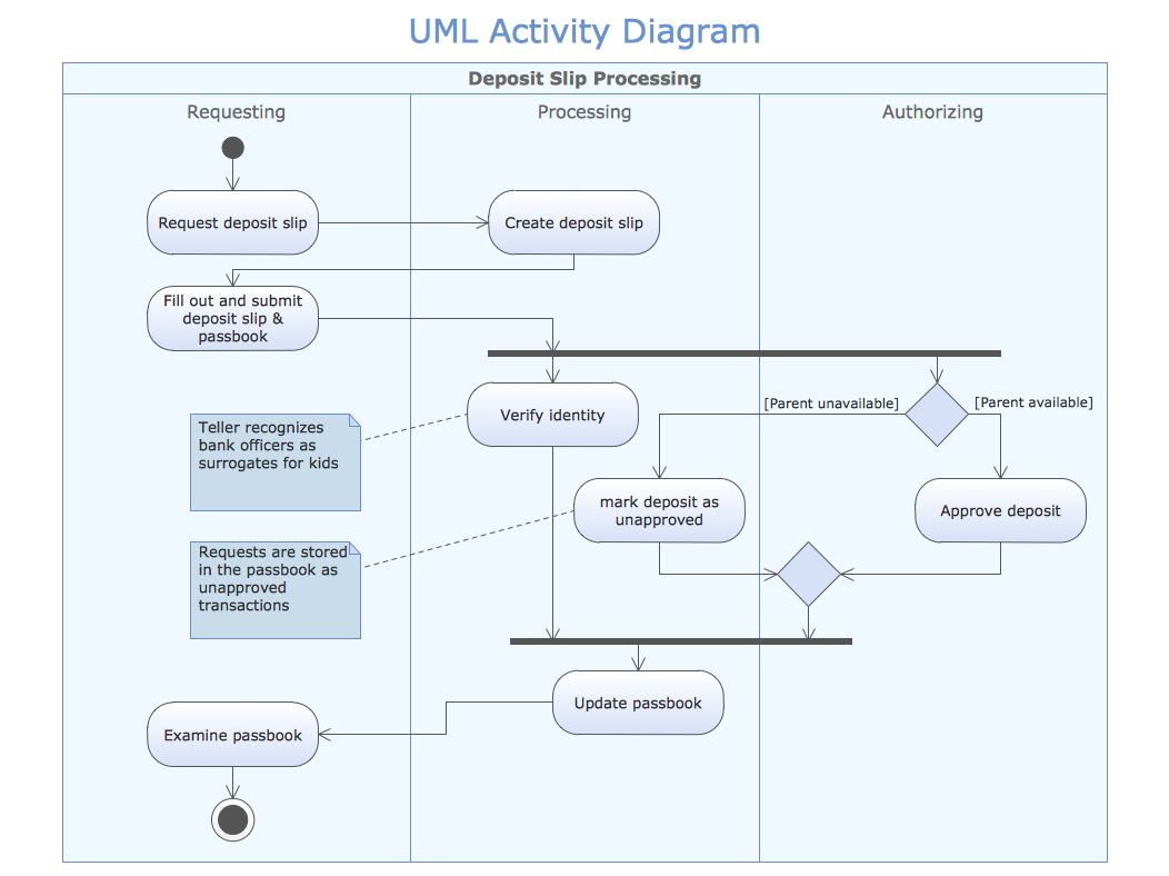

State machine diagrams document the various states a system can reach. Sequence diagrams show the order of messages that are passed between the elements of a system to complete a particular task or use case.

Test cases and derived requirements are linked to requirements with a dashed connector and an appropriate label.Ī use case diagram all of the ways an end-user interacts with your systems. Non-functional requirements can be specialised in the following ways.Ĭontained requirements are indicated with a circle with a vertical cross at the parent requirement. non-functional - a quality criteria to test and evaluate the performance of a system and whatever it outputs.functional - these requirements must be met.They include descriptive test cases to ensure requirements are tracked and met during implementation. (SysML only)Īlso called detailed specification diagrams, requirements diagrams show how the different requirements are related to each other and design elements.

SysML requirements models are created early in the process to define and refine customer requirements. Many of the SysML diagrams are the same or very similar to their UML counterparts - this is noted when each diagram type is introduced below. Tip: Style the shapes with colour to more clearly differentiate between types of elements, different groupings or regions. While you could create many of the diagrams with the UML shape libraries, the block shapes with ports, constraints and flows are in the SysML shape library.


 0 kommentar(er)
